 Honeywell Braukmann T104F Manual" width="" />
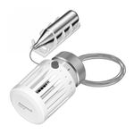
and valve actuator, connected by a capillary tube to a sensor.
The T104F Control attaches to the valve body by threaded
connections and may be mounted at any angle. Install the
remote sensor beneath the heating coils in the cold air re-
turn, or on a nearby wall where the air flow is not restricted.
The setpoint dial has reference marks (1-6). The control
has a low limit of 43°F (6°C) when the dial is turned fully
clockwise to the frost protection mark*. The red button
indicates the 68°F (20°C) setpoint limit. Higher settings may
be made by holding in the button while turning. The thermo-
static sensor is protected by a safety spring against tempera-
tures to 125°F (52°C).
MATERIALS OF CONSTRUCTION:
Body: Industrial grade plastics with low thermal
conductivity.
Fastening Ring: Plated brass.
Internal Parts: Brass thermostat capsule, other metals.
TEMPERATURE RANGE: 43° to 79°F (6° to 26 °C).
MAX. SENSOR TEMPERATURE: 125°F (52°C).
MAX. OVERALL DIMENSIONS: 2-1/8 in. (54 mm) wide,
3-5/16 in. (84 mm) long. See Fig. 1.
CAPILLARY LENGTH: 6 ft. 8 in. (2 m).
TEMPERATURE SETTINGS:
These are the setpoint temperatures, which correspond
to the setpoint dial reference marks, under ideal conditions.
Factors affecting the temperature at the sensor vary for each
installation. It may be necessary to adjust the setpoint
higher or lower to obtain the desired space temperature.